How To Assemble Basic Electronic Components With GSM Module?
It is better to draw a rough notebook sketch of the helmet before starting this project because it will allow us to understand the placement of components better and assembling the circuit will be easy for us. An excellent approach before starting the work is to make a complete list of all the components to save time and to avoid the chance of getting stuck in the middle of the project. A complete list of all the components that are easily available in the market is given below:
Step 1: Components Used (Hardware)
Step 2: Components Used (Software)
Step 3: Block Diagram
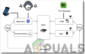
To demonstrate the working of the helmet well I have made a block diagram that is shown below:
Step 4: Working Principle
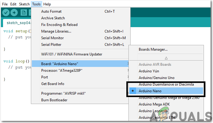
All types of Arduino boards can be used in the project but I preferred Arduino Nano because two of them will be placed inside the helmet and they require less space. I have used Alcohol sensor MQ-3 to determine the quantity of Alcohol the driver has taken and this level is indicated with a Bi-Colour LED. If the driver has taken a large amount of alcohol the LED turns Red and SMS notification is sent to the number mentioned in the code through a GPS. If the LED turns Yellow it means that the alcohol level is moderate and if it turns Green it means that the driver isn’t drunk. Hence, this ensures the safety of the driver and the risk of an accident is minimized to a great extent. The Ultrasonic sensor will be placed at the back of the helmet and it will keep calculating the distance between the rider and the vehicles at the back. If a vehicle is approaching the rider at a very high speed the ultrasonic sensor will send a signal to Arduino to trigger the buzzer and hence the rider will get aside and let the vehicle pass by. I have included the GPS module to send alerts to the specific mobile number in case of an accident. For detecting the accident the vibration sensor is included in the circuit that can be tuned to a specific level of vibration and immediately tells the GSM module to send a notification to certain numbers as a call for help. Two Arduino’s will be used in this project. One will be connected to the Ultrasonic Sensor and Alcohol Sensor and the other one will be connected to the GSM module and the vibration sensor. There will be two separate circuits that would be placed inside the helmet and they will be connected to the same battery. Note: The variable capacitor present in the vibration sensor will be tuned.
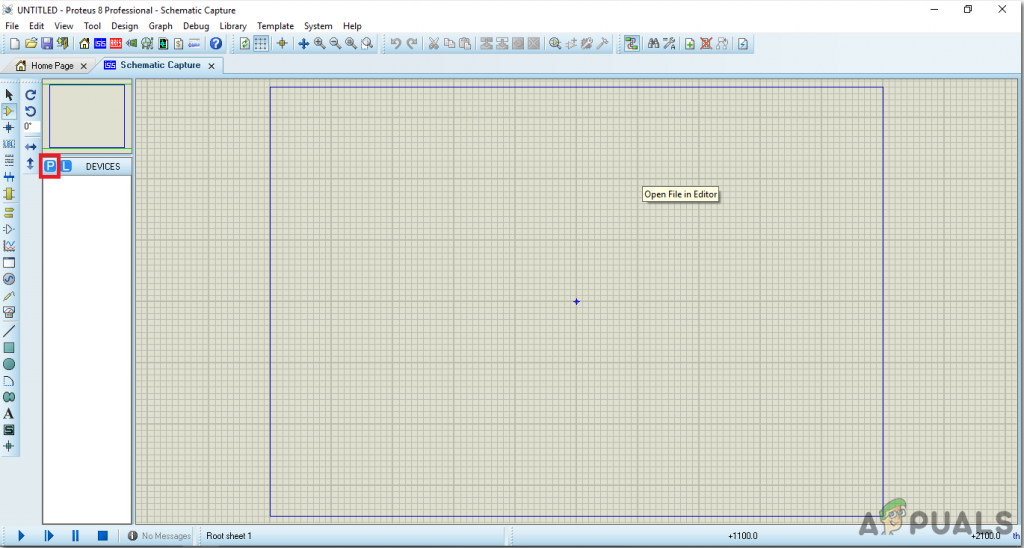
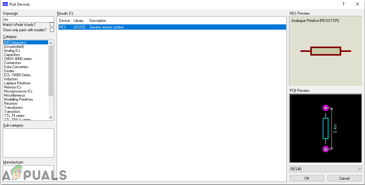
Step 5: Assembling The Circuit On Proteus
Step 6: Circuit Diagrams
Assemble your hardware circuit according to the circuit diagrams shown below:
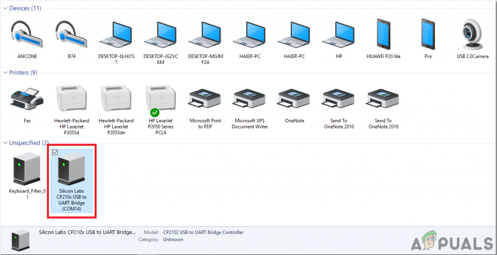
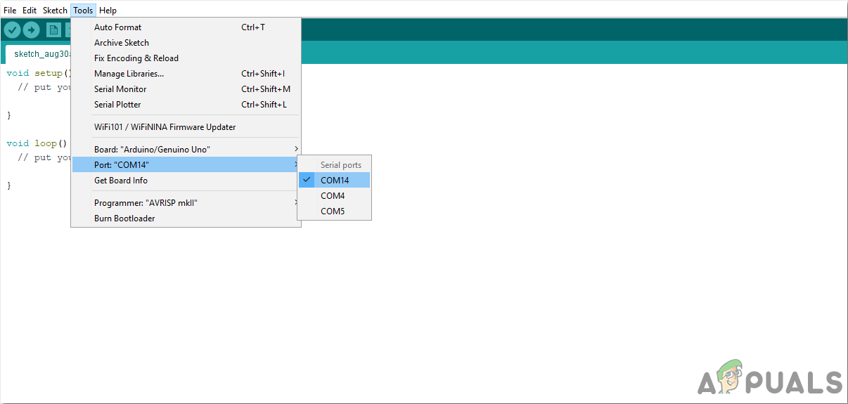
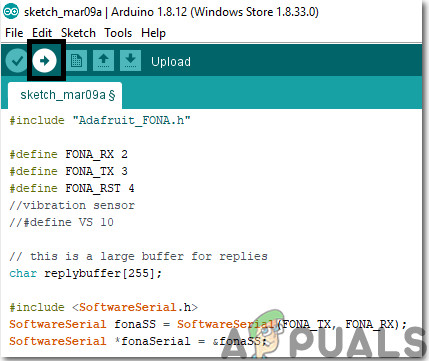
Step 7: Getting Started With Arduino
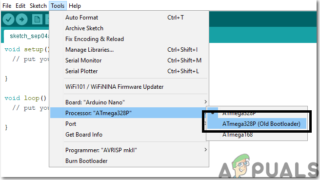
If you are not familiar with Arduino IDE before, don’t worry because below, you can see clear steps of burning code on the microcontroller board using Arduino IDE. You can download the latest version of Arduino IDE from here and follow the steps below:
Step 8: Code Of The Project
The code is a bit lengthy but it is really simple. Some of its chunks are explained below:
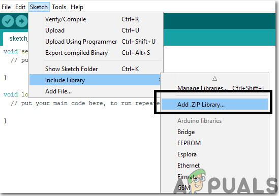
- At the start, libraries are included so that we can easily communicate with special peripheral devices.
- Then pins are defined on the Arduino nano which will be used to connect the external sensors to the microcontroller. These pins will be responsible for the Input and Output of the data in the microcontroller.
- Then different variables are initialized which will later be used in the calculation processes during the run time of the code. A buffer is also made that will be used with the GSM module.
- void setup() is a function that is executed only once when the microcontroller is powered up or the enable button is pressed. the baud rate is set in this function which is basically the speed in bits per second by which the microcontroller communicates with the external sensors. All the pins of the Arduino are initialized here that they will be used to take input from the sensor or send output to another device. GSM module is also initialized in this function.
- void loop() is a function that runs repeatedly in a loop while the microcontroller is powered on. A code is written for an ultrasonic sensor that if it measures a distance less then a specific value, it will send a signal to the buzzer which will be used to notify the rider that a vehicle is approaching near. The gas sensor is also integrated here. Three LEDs are used in order to tell that if the rider is heavily, partially or less drunk. If green LED glows, it means that the rider is good to go. At the end of this function, another function is called named viberationFun().
- viberationFun() is a function that will detect if the bike had a collision with another object or not. If it detects any collision, it will send a message to the numbers that are specified in the code. In this way, the news of the accident will reach someone else who will take the necessary steps to save the rider.
Step 9: Assembling The Hardware
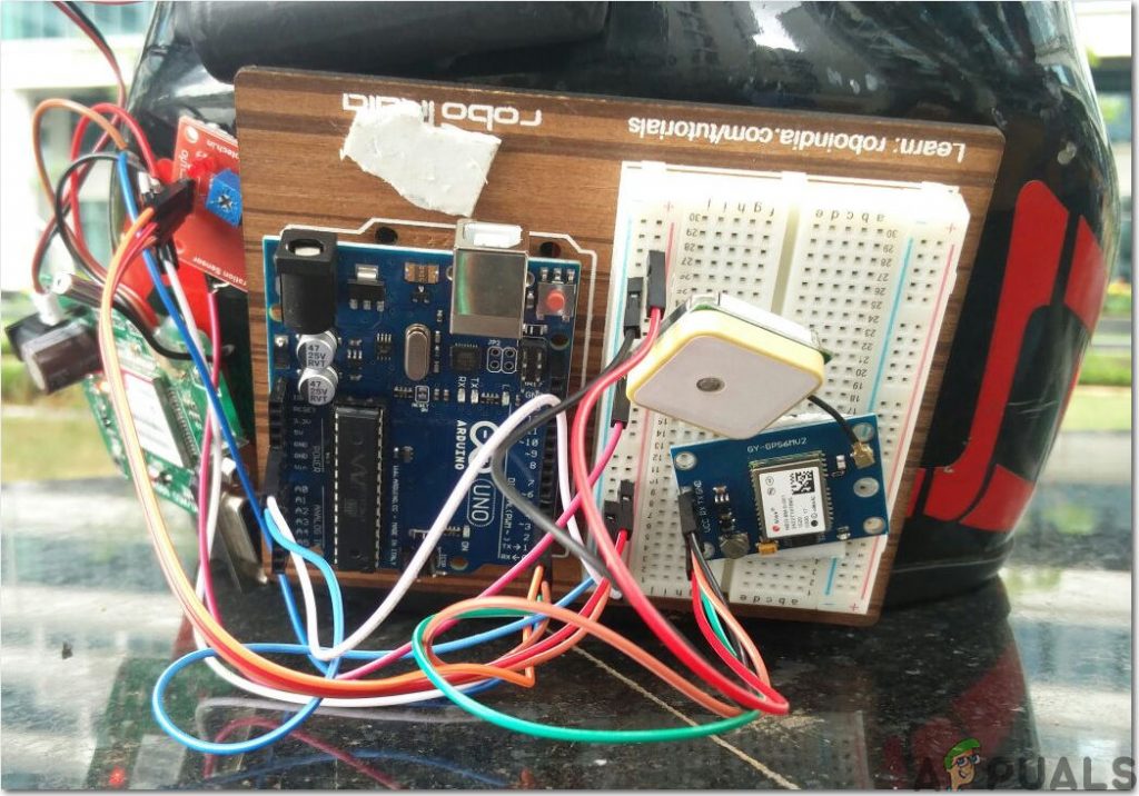
Now, as we know the main connections and also the complete circuit of our project, let us move ahead and start making the hardware of our project. One thing must be kept in mind that the circuit must be compact and the components must be placed close. Veroboard is the better option as compared to the breadboard because connections get loose on the breadboard and short circuit can take place and breadboard has more weight as compared to the Veroboard. The circuit placed on the Veroboard will be very small so it can be fitted inside the helmet easily. The rest of the circuit will be placed inside the helmet except the Ultrasonic sensor that will be mounted on the backside of the helmet to detect the vehicles coming from behind. Lipo battery is used in this project because it is a very lightweight battery and even if the rider is going on a long trip it can give better timing. Adjust the Lipo battery inside the helmet because due to harsh weather conditions like rain it can result in failure of the circuit.
Step 10: Testing
As now, the hardware is assembled and the code is also uploaded onto the microcontroller let’s go through the final step and test the circuit. Sit on the motorbike and turn ON the push button switch to activate the circuit. Start riding in your street and ask someone to approach you on the car at a high speed from behind. You will observe that the buzzer will start ringing and after that apply brakes at a high speed so that large vibration can occur. As soon as the vibration occurs an alert notification will be sent to the mobile number that you’ve mentioned in the code.
Recommendations
This is a very interesting project there are several options that can be included further in it with the help of some basic electronic components. Some of them are illustrated below:
How to Factory Reset Your Google Home Smart SpeakersHow to set up and Configure your Google Home Smart SpeakersHow To Make Smart Home Automation System Using ESP32 Module?Using Hogar Controls: For Smart Home Automation