555 Timer IC is the heart of this circuit. This IC will control the operation when the finger will be touched on the respective plate. So, the final system will be fully operational and will perform the switching by just a single touch.
How To Use Touch Plates In The Circuit Design?
As we know what we want to do in this project, now let us move ahead and gather some more information to immediately start working on this project.
Step 1: Components Needed (Hardware)
If you want to avoid any inconvenience in the middle of any project, the best approach is to make a complete list of all the components that we are going to use. The second step, before starting to make the circuit, is to go through a brief study of all these components. A list of all the components that we need in this project is given below.
Step 2: Components Needed (Software)
After downloading the Proteus 8 Professional, design the circuit on it. I have included software simulations here so that it may be convenient for beginners to design the circuit and make appropriate connections on the hardware.
Step 3: Design of The Circuit
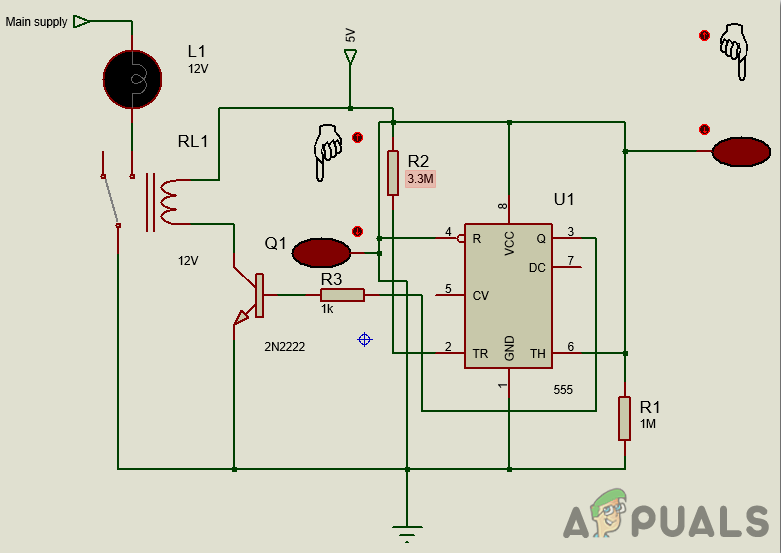
The design of this circuit is quite simple. The ground, Vcc and Reset pins of the 555 timer IC are connected to 5V and ground. A 3.3M-ohm resistor is used and the pin3 of the 555 Timer IC is pulled HIGH. Pin6 of the 555 Timer IC is pulled down by using a 1M-ohm resistor. Both of the touch plates are directly connected to pin2 and pin6 of the 555 Timer IC. When we touch the ON plate, one end connects to the pin2 and the other gets connected to the ground. In the same way, one end of the ON plate is connected to pin6 of the timer IC and the others connected to 5V. Pin1 of the 555 Timer IC is the ground Pin. Pin2 of the timer IC is the trigger pin. the second pin of the Timer IC is known as the Trigger Pin. If this pin is directly connected to pin6, it will work in Astable mode. When the voltage at this pin drops below one-third of the total input, it will get triggered. Pin3 of the timer IC is the pin where the output is sent. Pin4 of the 555 Timer Ic is used for the reset purpose. It is initially connected to the positive terminal of the battery. Pin5 of the timer IC is the control pin and it does not have much use. In most of the cases, it is connected to the ground through a ceramic capacitor. Pin6 of the timer IC is named as the threshold pin. pin2 and pin6 are shorted and are connected to pin7 to make it operate in Astable mode. When the voltage of this pin gets greater than two-third of the mains voltage supply, the Timer IC will come back to its stable state. Pin7 of the Timer IC is used for the discharge purpose. The capacitor is given the discharge path through this pin. Pin8 of the timer Ic is directly connected to the ground.
Step 4: Working of The Circuit
As we now know the abstract off out project and we also have a basic idea of how our components work, let us move a step ahead and understand the main working of our project. When the circuit is connected properly and the power is applied to it, just simply touch the ON plate to switch on the circuit and touch the OFF plate to switch the circuit off. The device connected to the relay module will remain in the off state even if the power is applied to the circuit. When the circuit diagram is observed, we will come to know that the pin6 of the timer IC is pulled LOW and the pin2 of the timer IC is pulled HIGH. So, when the ON plate is touched by the finger, the state of the pin2 of the 555 timer IC will become LOW. As the state of the pin6 of the timer IC is already LOW, this will result in the HIGH state output at pin3 of the timer IC. This HIGH signal will be sent to the transistor. This transistor is working as the switch for the relay. It will switch on the relay and the circuit will be completed resulting in the bulb to switch on. Now, the OFF plate is connected to pin6 of the timer IC and it is pulled down. If the OFF placed is touched, it states will convert from LOW to HIGH for an instance. This will result in the LOW state of the output at pin3 of the timer IC. As a result, the transistor will be switched OFF and ultimately the relay connected to the transistor’s output will be switched off. This will switch off the bulb connected to it. The main working of this circuit is just like a flip-flop. When the plate is touched, the bulb will turn on and when the plate is touched again, the bulb will turn off.
Step 5: Designing the Touch Plates
The most important part of this project is the touch plates because the switching is purely based on touch. There is no need to use special touch plates in this circuit. A simple way to make touch plates for this project, at your home is shown below. To make the touch plates, two pieces of 2cmx2xm copper clad board are required. Take the copper clad board and make a cut in it in such a way that the board does not break completely but still, the upper layer of the copper gets separated by a complete cut. If you cant make these at home, small touch plates can be found in toy cars. These plates are generally made of carbon. This carbon is mounted on silicon rubber. The block and the pad come in contact when this plate is pressed. As soon as these two come in contact, the resistance between them decreases. Those pads that are available in the market are very effective and protected from corrosion. But the plate that is made at home is also efficient but very low in cost. It also works in the same way i.e. the resistance drops to a large extent when a finger is touched on the plate, because of the moisture on the finger.
Step 6: Assembling The Components
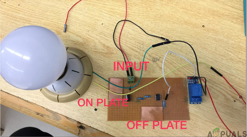
Now, as we know the main connections and also the complete circuit of our project, let us move ahead and start making the hardware of our project. One thing must be kept in mind that the circuit must be compact and the components must be placed so close. The circuit will look like the image below:
Applications
There is a wide range of applications of this Touch Plate based switching circuit. Some of them are listed below: