How To Design Anti-Theft Ignition Circuit?
Now as we know the abstract of the project, let us move forward and gather different information to start working. We will first make a list of the components and then assemble all the components together to make a working system.
Step 1: Components Needed (Hardware)
Step 2: Components Needed (Software)
Step 3: Block Diagram
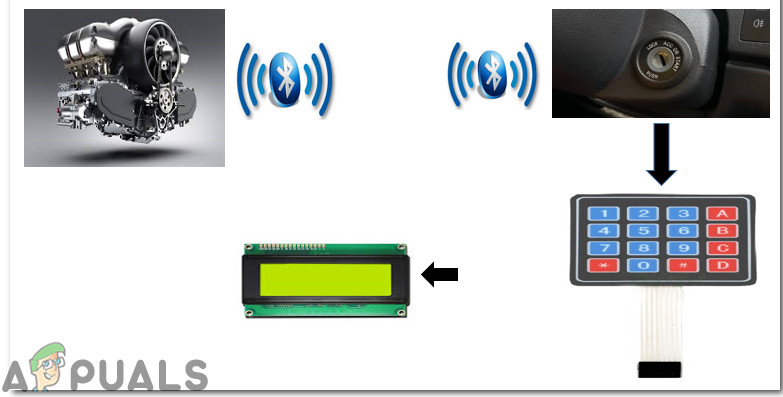
In this project I have designed two block diagrams to elaborate the purpose of the project clearly. First one shows the traditional ignition system that is most commonly used in all of the cars that are assembled nowadays. The second one shows our ignition system that I have designed in this project that can be installed in the cars to make them more secure.
Step 4: Working Principle
In our ignition system, the wires will not be controlled by the On-Board Diagnostics Port but they will work autonomously. There are several electronic gadgets available in the market that have the ability to reset the OBD Port and the computers that are present in the engines. The electronic circuit will have two portions. One will be installed at the ignition switch side and the second one will be placed at the engine side. Wireless transmission of the Bluetooth signals will take place between these two sides. The primary circuit will comprise an ignition switch, Arduino, LCD, keypad and HC-06. The secondary side of the circuit will comprise of an Arduino, Relay module, HC-06, and buzzer. As soon as the key moved to start the car the LCD is turned ON and allows the driver to enter the password that is set by him/her initially in the Code. If the driver enters the correct password only then the signal is received at the engine side by the Bluetooth module and the key is moved further that will trigger the Relay circuit and the fan will be turned ON. Now, in order to start the car, we need to move the key towards the ignition position that will allow the car to be started. As soon as the car is started the system will display ON on the LCD and as soon as the key is moved in reverse position the car will be turned OFF but the wireless connection remains until the key isn’t fully moved backward. If the multiple wrong attempts are done to start the car then the alarm is generated using the buzzer that will alert the people passing by or the owner of the car if he/she is not far away from the car.
Step 5: Simulate The Circuit
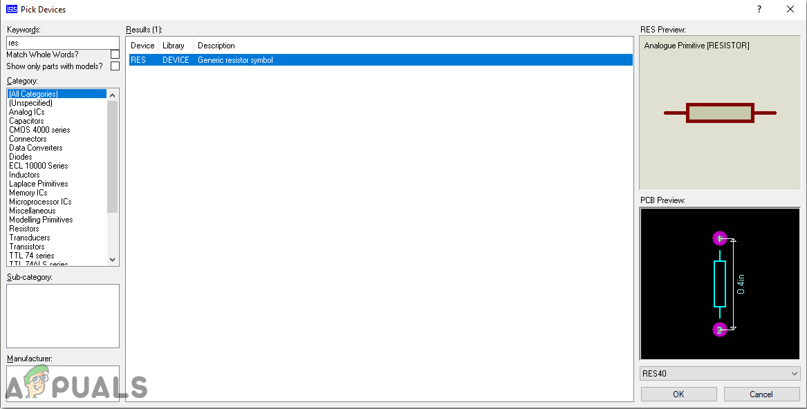
Before making the circuit it is better to simulate and examine all the connections on a software. The software we are going to use is the Proteus Design Suite. Proteus is a software on which electronic circuits are simulated.
Step 6: Circuit Diagrams
Step 7: Getting Started With Arduino
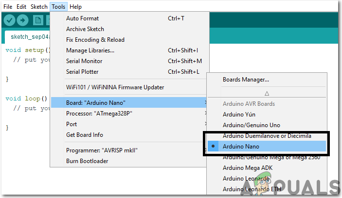
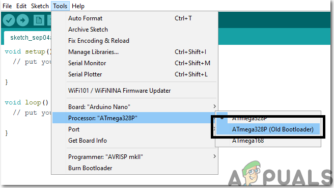
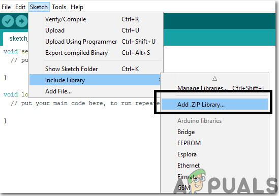
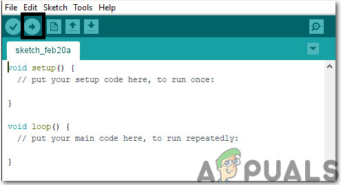
If you haven’t worked on Arduino IDE before, don’t worry because a step by step to set up Arduino IDE is shown below. Download the code and necessary libraries by clicking Here.
Step 8: Code
The code for this project is pretty simple and well commented.
Step 7: Hardware Design
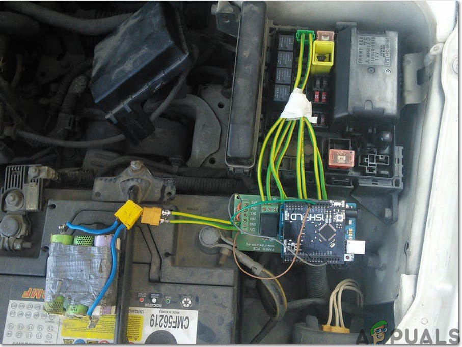
As we have now simulated the circuit on software and understood the code, now let us move ahead and place the components on the Breadboard. Firstly, we will assemble the primary side circuit and then we will assemble the secondary side circuit. It is better to connect the circuit with the audio system of the car so that it will be difficult for the burglars to find that circuit and they will take more time to reach behind the dashboard of the car because it will be placed behind it. The audio system of the car will be connected to the switch and further to the DC battery to turn ON the audio system. When the user enters the correct password by using the 4×4 keypad the wireless connection is established between both sides and he/she will have to rotate the key again to start the car. Assemble all of the connections on the breadboard and use double tape to paste the circuit behind the audio system of the car. Now, we will assemble the secondary side of the circuit that is also known as the engine side. At this side, we will connect the Relay module with the Arduino and it will be triggered only when it receives a signal from the Bluetooth module. If the driver enters the wrong password in multiple attempts then the alarm will start ringing and people passing nearby will become to know that there is some issue in the car. Place the components on the breadboard according to the circuit diagram shown above and attach the circuit to the radiator water bottle.
Recommendations
How to locate your LENOVO Serial NumberEverything You Need to Know Before Buying a 6.5 Speaker for Your CarFix: The VPN Client agent was unable to create the interprocess communication…Fix: Android Auto Communication Error 8
